Shift registers are short delay lines using a clock with a variable rate to read and write a value. Imagine shift registers looking a bit like a pipe with an input on the left opening and an output at the right opening. On each clock pulse on a clock input a value will enter the pipe. After a certain amount of clock pulses that input value will appear at the output. So, it is like all input values are shifted in a first-in-first-out order through the pipe. This first-in-first-out order is the reason why shift registers are also named FIFO-buffers.
When using analog circuitry the most basic form for a shift register is a bucket brigade made with a number of capacitors that act as memory cells charged with a voltage level and switches that pass the charge from one capacitor to the next. In the seventies chips became available that held a long string of capacitors and switches on one silicon substrate, with lengths of up to 4096 steps. These bucket brigade devices, or BBD’s, have the advantage that they can be clocked with a variable clock rate from as low as 10kHz to a maximum around several hundreds of kHz, which is perfect to create audio delays with delay times of up to several tens of milliseconds. Varying the clock rate creates a smoothly varying time delay, which creates a smooth frequency sweep on a sound with a fixed pitch. These chips were frequently used in flanging devices, chorus units, echo devices, resonators, comb filters and early implementations of pitch shifters. The chips had great disadvantages as well, like being noisy, having quite some signal loss from input to output and generating quite some harmonic distortion. Still, used in a well-designed schematic they could have a very lush sound with a typical ‘analog’ character. These days bucket brigade devices are replaced with digital memories using an A/D converter on the input stage and a D/A converter on the output stage. There is a very important difference between using BBD’s and digital memories as the early bucket brigade devices have a fixed length and a variable clock rate, while modern digital memory designs in general have a fixed clock rate and a variable length. What this means is that delay devices based on digital memory must use elaborate interpolation to fight the aliasing created by the delay time being related to the fixed clock rate. This aliasing is especially troublesome when creating a smooth frequency sweep. If the sweep is very fast the digital delay line will also start to skip memory locations and thus loose information, resulting in degradation of the sound when the delay line output it is fed back to the delay line input. Having to compensate for these skips will make the anti-aliasing routine quite complex, as an average value of the skipped samples must be calculated and taken into account. In contrast, fixed length with variable clock rate delays do not suffer from dataloss as values are never skipped. All in all, both bucket brigade devices and digital memory delay lines have troubles of their own and it is not easy to create a proper digital emulation of analog effects based on bucket brigade chips.
Short bucket brigades can be used as musical sequence and pattern generators that can create evolving patterns. Such pattern generators can be represented as a certain amount of sample and hold modules chained in series. Such a chain is usually named a shift register. Imagine there is a chain of eight sample and hold modules and they are all clocked with the same clock. On each positive edge of the clock signal the value in a sample and hold is passed on to the next sample and hold. To prevent that the value on the first sample and hold is raced to the output of the last sample and hold each sample and hold output must be buffered with an extra sample and hold that is clocked on the negative edge of the clock signal. This is essentially the same as what happens in a bucket brigade, where twice as many men are needed as the amount of available buckets to pass on the buckets. This technique of using the positive edge to clock values and a negative edge to clock buffers is sometimes named double clocking. An alternative approach to double clocking a bucket brigade delay line is to use an electronic multi-pole switch that is advanced to the next position on each clock pulse. E.g. a circular delay line of eight steps can be created when a single sample and hold circuit is equipped with e.g. an eightfold multi-pole switch, which on its turn is connected to eight capacitors. The trick is now to always advance the multi-pole switch to the next position on a clock pulse, but have a mechanism that can prevent the currently selected capacitor of being charged with the voltage on the sample and hold input. This creates a circuit that is equivalent to an eight-step clocked delay line where the output of the delay line is by default connected to the input of the delay line by a toggle switch. You can imagine that it now seems impossible to enter something into the delay line, but when the input toggle switch is toggled to input a value from e.g. an LFO during exactly one clock pulse period this value is entered into the delay line and will appear on the output each multiple of eight clock pulses later.
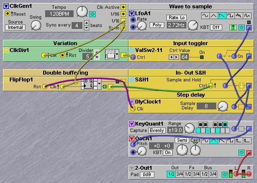
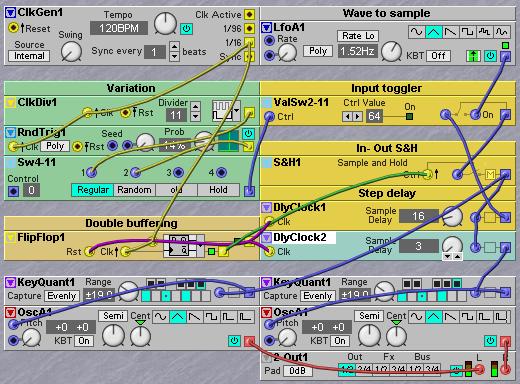
This circular delay line is a very powerful means to create repeating patterns where now and then one or more values in the pattern are replaced by other values. On the G2 it would look like this:
The circular delay line is made with one S&H module plus a ClockedDelay module. By using double buffering the amount of steps will be equal to the amount of steps set on the ClockedDelay module. The two clock signals are generated by a FlipFlop module, which is used in a way that the S&H module is clocked exactly one system sample after the positive edge of the clock signal coming from the ClkGen module. The reason why it is patched in such a way is to make sure that the input toggle switch is toggled to the signal input one system sample before the S&H is triggered. In this way the working of the toggle switch is always reliable. When the FlipFlop receives a positive edge on both its Clk and D inputs it will pass on the high value to the Q output. The Q output will clock the DlyClock module and make it shift the pattern one step. On the next system clock the FlipFlop will find a high value on its Rst input and reset the Q output to low and the Q-bar output to high. Now the Q-bar output will trigger the S&H, sampling he signal selected by the input toggling switch. If the input toggling switch selects the output of the ClkDelay module the value that is delayed eight steps will be entered into the ClkDelay again. But if the input toggling switch selects the output of the LFO module in the patch it will enter a brand new value into the pattern. The input toggling switch is controlled by a clock divider module that defines after how many clocks a new value is entered into the pattern. What you should do is rebuild the little patch in the example and play with it until you understand how patterns are built up. There are basically three parameters that define the build-up of a pattern. First is of course the length of the pattern, which can be set on the ClkDelay module. Second parameter is after how many steps a new value is entered into the pattern, which can be set on the ClkDiv module. Setting this value to 1 will make the circuit act like a normal S&H module sampling the LFO waveform. Note that if the ClkDiv module is set to an even number and the dleay length is also an even number the odd numbered steps in the pattern will not be changed, as they will be skipped by the ClkDiv module. This means that in many case you would probably want an even value of steps and an odd value for the ClkDiv, or instead an odd number of steps and an even value for the ClkDiv module. In many cases you also probably want the number of steps fixed, like e.g. eight twelve sixteen or thirtytwo steps and variate the value on the ClkDiv module. The third parameter is the rate, waveform and amplitude of the sampled LFO. If the LFO rate is very slow in comparison to the ClkGen clock rate new values will enter in the normal way, but it will take a long time until these new values actually change to a higher or lower value. You need to develop a feel for how the ratio between the LFO rate and the clock rate works out. As a rule of thumb it is good idea to start with the LFO rate faster as the ClkGen clock rate and control the speed of change of the pattern with the ClkDiv module. But you are free to experiment and find what works out best musically for a certain musical purpose.
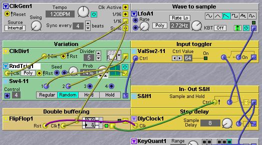
The beauty of this basic patch is that there are a lot of expansion possibilities that create an almost unlimited amount of way to build up, variate and build down sequences. E.g. the ClkDiv can be substituted for a RndTrig module, or a RndTrig is added and a two-pole switch is added to make it possible to select between a regular or a random rate of change in the pattern. By tweaking the Possibility knob on the RndTrig the average speed of change can be controlled between very fast at almost 100% and very slow at 1%. If set to 0% no new values will be entered into the pattern and the pattern will remain as it is. When a four-pole switch is used instead of a two-pole switch the third and fourth switch position can be connected ‘to nothing’ to cause the pattern to hold as it is. It would look like this:
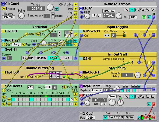
Another interesting option is to use an SeqEvent module to define when a new value should be entered into the pattern. When the SeqEvent module is clocked from the ClkGen Sync output and the event bar is set to the G-mode it is possible to change e.g. whole blocks of four, eight, sixteen steps, etc. It would look like this:
Another variation is to let a LFO decide when a new value is to entered. But this needs some extra facility, a little circuit that generates a pulse that is exactly as long as one step and is initiated by the LFO. Such a circuit is named a one-and-only-one and is made with two FlipFlop modules. The idea is to set a FlipFlop by a positive going zero crossing of an LFO waveform. The Q output of this first FlipFlop is monitored by a second FlipFlop that is clocked from the ClkGen module. If the second FlipFlop clocks a high from the first FlipFlop it will pass this high on to its own Q output. Noteh that this will happen on the positive edge of the ClkGen signal, so be in sync with the ClkGen module. The Q output from the second FlipFlop will also reset the first FlipFlop, so the when the next clock from the ClkGen comes it will clock a low from the first FlipFlop and set its Q output low. So, on the Q output of the second FlipFlop will be a pulse that is exactly as long as one step in the pattern. It looks like this:
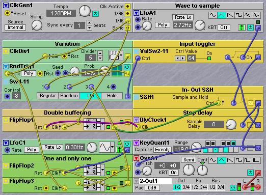
The LFO plus one-and-only-one circuit has the advantage that by modulating the LFO rate the rate of change in the pattern can be modulated in wild ways over a wide range.
This interesting effect is created by adding another clocked delay line in parallel to the DlyClock module. This second delay line will effectively delay the pattern by a number of steps and its output can be fed to a second oscillator module. As you can see in the next illustration it is quite simple to add this effect:
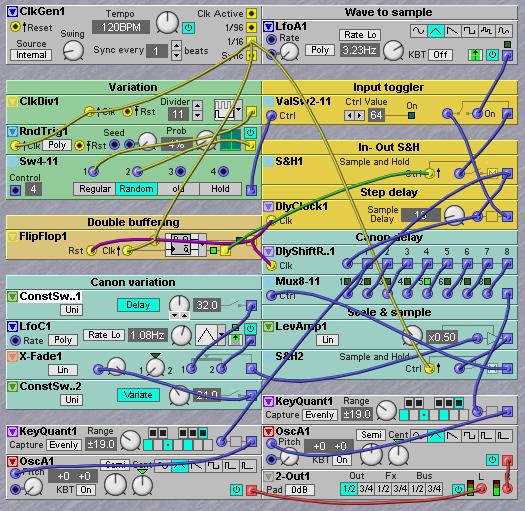
The next step is to create variation in the canon effect. By replacing the second ClkDelay module by an eight output DlyShiftRegister module and using an eight input MUX module the amount of delay steps of the canon effect can be varied with a control signal from e.g. an LFO. To get the change in the canon in sync it is necessary to use a S&H module between its control input and the LFO output. This S&H must be clocked from the ClkGen module. There is some extra modules needed to scale the LFO signal down and combine it with a fixed setting to keep it in the MIUX control range between 0 and 32 units. As you can see this is neatly solved by crossfading between a Constant module and the positive only LFO waveform, after which the result is scaled down by a factor of 50%. Then it is synchronized to the ClkGen by the S&H module. It all looks like this:
The previous examples tried to show how to build up a pattern generating patch that can create varying pattern where there is some sort of a controlled amount of repeat in the patterns. The like of thinking that led from one example to another can be extended into virtually infinity. E.g. instead of sampling a LFO waveform it is also possible to sample sequencer modules with preset sequences. By having a several sequencer modules and dynamically selecting which one to use you can morph preset patterns into each other. It is also possible to add a second circular buffer on the output of the first one, fill this one one a moment that the pattern sounds really interesting and hold it there. Then you can use this second buffer to later fill the first one again with that previous interesting pattern. Just think of how you could patch such a system and try it. It is very well possible that you end up with something that is even more interesting.
By replacing the oscillator modules by MidiOut modules you can let other instruments, like e.g. a sampler, play the generated patterns. Or record the patterns into a MIDI sequencer program. This last option can be very interesting, as whenthe MIDI information has been recorded you can easily delete the less interesting bars and move the more interesting ones around to more fit the structure of a song.