
This chapter is about the type of filters that are commonly used in the individual voices of an analog synthesizer patch. To deepen your practical understanding of filters the Nord Modular G2 will be used to build your own filter types.
The original idea behind the classic VCO->VCF->VCA ‘subtractive synthesis’ patch, is actually based on how acoustic instruments work. In this ‘mother of all analog synth patches’ an oscillator signal goes into a filter and then into a controllable amplifier controlled by an envelope signal. Let’s first look at a real-world example; an acoustic string instrument. This instrument will have a resonant body and strings will be attached onto this body in a way that the body can be made to resonate. The resonant body is very important, without it there is only very little sound. What happens in this string instrument is that the vibration of the string is transfered onto the resonant body and the resonance will give the sound its volume and timbre. It is the kinetic energy of the vibrating string that excites the resonant body, and the resonant body transforms the energy from the string into the ‘body of the sound’. The strings will define the pitch and the shape and material of the resonant body will define the overall timbre. In general a resonant body will easily resonate in some parts of the sound spectrum and less easy in other parts. This will favour some frequency bands in the spectrum and these frequency bands are named formant areas, as they ‘form’ the timbre of the sound.
It was exactly this principle of an exciter, which controls the pitch, and a resonator, which shapes the timbre, that inspired early synthesizer designers like Bob Moog to use a resonant filter driven by an oscillator to create sounds. The oscillator acts as the exciter and the resonant filter shapes the timbre by creating a formant effect at the resonant frequency of the filter. Waveforms with sharp edges, like a sawtooth wave, can strongly excite the resonance in a filter, turning the filter into the electronic equivalent of an acoustic resonant body. A good example of a filter that lets iteself be excited very well is the resonant ‘four-pole ladder filter’, designed and patented by Moog in the early sixties. This filter turned out to be só useful musically that many people still considered it the best type of filter around. These days’ digital modular synthesizers come with several filters and undoubtedly one of them is an emulation of the ladder filter. But the digital emulations have one disadvantage over analog filters, which is that they are often too perfect. The Moog ladder filter was in practice far from ‘theoretically perfect’, due to wide component tolerances and small non-linear imperfections in the components. Apparently the imperfections in the Moog filter add to the sound in a positive way. It is a good idea to try to build a filter yourself to understand better why certain filters can have a certain sound. With the DIY filters descibed in this chapter you can explore the inner workings, deliberately add imperfections and make any possible variation on filtertype and slope steepness within the concept of the typical four-pole filter.
The Moog ladder filter is made by cascading four basic filterblock sections that each have a cutoff slope of 6dB per octave. An individual filterblock section is commonly named a pole, a name derived from a parameter when doing calculations while designing a filter. A pole is not really an actual discrete electronic circuit, but as many manufacturers have used the word pole for so many years it has become common to talk about two-pole filters, four-pole filters, multi-pole filters, etc.
When a digital modular synthesizer has a couple of 6dB lowpass filters present it is actually possible and quite easy to patch filters like the four-pole filter yourself.
In a resonant four-pole filter the poles are cascaded in series and the output signal at the end of the cascade is fed back to the input of the first pole to create a feedback loop. Feedback is very important as feedback is always necessary to create resonance. Each of the four poles will cause a very short delay on the signal. This delay is only 1/8th of the length of a single cycle of a waveform tuned to the pitch that is equal to the cutoff frequency of the filter pole. The four poles together will cause a total shift of four times 1/8th, so one half of this waveform cycle. If this delayed signal is additionally reversed in phase this ‘inversion’ will create an additional ‘phaseshift’ of another 180 degrees. This causes the delayed and inverted waveform at the output of the four poles to appear to have a delay of exactly a full cycle of the waveform, and so lag one cycle of the waveform behind in respect to the input signal. But note that it is only a sinewave component at a pitch that is equal to the cutoff frequency of the filter that will have this exact one cycle delay. Partials in the sound that are not at this cutoff frequency will have different phaseshifts. If the delayed and inverted signal is fed back to the input of the four poles it will reinforce the input signal and thus create the wanted resonance. In practice the input signal is mixed with the feedback signal before entering the first pole and output is taken from the output of the last pole. This will give a cutoff slope of 4 times 6dB, so 24dB. The resonance is defined by the amount of feedback. An important thing to remember in your experiments is that to make the filter resonant the feedback signal must always be inverted or phase reversed to be able to cause resonance, without this phase reversal the filter won’t resonate at all. This also applies when using two, three or more than four poles in your filter design. By using a G2 two-input mixer module with an invert button on its inputs, the phase reversal can be simply done by pressing the proper invert button.
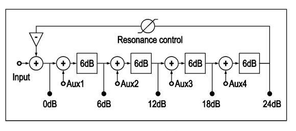
Following is a schematic of the classic four-pole filter.
On the G2 a basic DIY 24dB filter patch looks like this:
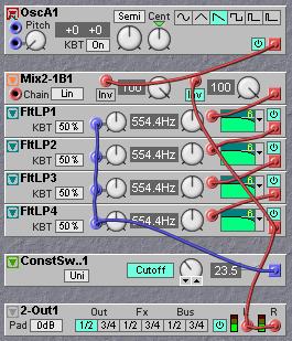
A sawtooth oscillator is used as the sound source. The input to the filter is the first input on the mixer, the knob on the second input of the mixer is the resonance control. Note that the second input has the Inv button light up to show that it inverts its input signal. So, this invert button causes that phase reversal that is necessary in the resonance feedback loop. When patching this little patch and experimenting with the resonance knob there are some ‘flaws’ that can be easily noticed. First observation is that the overall volume drops slightly when the amount of resonance is raised. The apparent drop in volume when the resonance is opened is in fact a property of any basic 24dB lowpass filter. In practice this is often compensated by adding some extra input signal when the resonance knob is opened. The second observation is that the resonance is only shallow at 100% feedback. This means that adding extra amplification in the feedback path must increase feedback over 100% here. Theoretically the resonance feedback signal must be amplified by 12dB for full resonance, as each 6dB filterblock attenuates –3dB at the cutoff/resonant frequency. A third observation is that it would be nice to make the resonance modulatable, which can be done by inserting a multiplier module in the resonance feedback path. These three features can be accomplished by adding only two modules, a two-channel mixer and a multiplier.
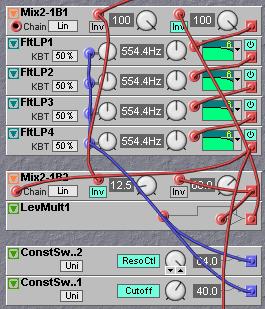
The two-channel mixer is inserted after the fourth pole and the output of the fourth 6dB filter is fed to the Chain input of the mixer. The output of the mixer is connected to the input of a multiplier and the output of the multiplier is connected to the resonance feedback input on the first mixer. It should be obvious that the multiplier can now be used to set the resonance by a control signal. The simplest way to raise the gain of the feedback loop is to raise the gain of the second mixer beyond unity gain by connecting its output to the second mixer input and feeding a little bit of the mixer output back to this input. This connection of a mixer output to one of its inputs will change the mixer into what is named an integrator circuit. To understand what this connection does you must realize that an input on a G2 mixer module will see its own current output sample as a previous sample. Take in mind that the DSP calculates the patch 96000 times a second. When in a new calculation a module input is taking a value from the modules’ own output, the output value to use must have been calculated in the previous calculation round, simply as the output value for this new calculation round is not yet finished, as in fact the module is just about to be calculated. What this means is that this feedback connection has a time delay of exactly one sample, and the output value is what is named the Z-1 sample value. So, the output of a mixer on the G2 system acts as what is named a Z-1 sample to its own input. The effect of an integrator is that it will create a small high frequency damping and act on an audio signal as a soft lowpass filtering. An integrator is often used to make a circuit with a feedback loop more stable in the high frequency ranges. In analog circuitry it is often used to prevent radio frequencies to leak into the audio circuit. In digital systems it is used to prevent feedback systems to start resonating on half the sample rate with the side effect that the sound also sounds a bit warmer and more like analog circuitry.
What the integrator feedback connection means for the four-pole filter is that in this mixer module with its feedback connection, the lower and middle frequencies are boosted more than the higher frequencies in the resonance feedback loop. This causes a small high frequency damping that in practice makes the resonance more stable at high cutoff settings and the additional advantage of giving the DIY filter the warm sound of an analog filter.
To tune the resonance range first open the resonance feedback knob on the first mixer fully and feed a value of +64 to the multiplier control input. Then close the second input knob on the second mixer before making the mixer feedback connection. When the connection is made start to slowly open the input knob. You will hear the resonance becoming more pronounced. When the knob display is around a value of 75 the resonance has become sÛ high that it will make the filter go into selfoscillation. Turn back the knob slightly until the display shows 68. At this setting the resonance is quite pronounced and musicalkly very useful, but the filter will not yet go into selfoscillation. Now tweak the control signal on the multiplier control input between 0 and +64 and you hear that the patch has proper resonance control.
The drop in volume at a higher resonance can easily be corrected by feeding a little bit of the input signal to the second mixer. Note that as the output of the second mixer is inverted at the second input of the first mixer the input signal fed to the second mixer must be inverted as well to work correctly. When the resonance is increased a little bit of the input signal is added through the gain control that sets the resonance. More resonance will also add more input signal and correct the output level. How much the mixerknob for this extra input signal must be opened can best be set by ear. Tune it in a way that the apparent loudness at high resonance settings is about equal to the loudness at no resonance.
This 24dB filter design is a good base for doing all sorts of filtertricks. In the example the four 6dB filters are tuned to the same cutoff frequency, just like in the original ladder filter. But it is fun to set them to slightly different frequencies and/or give them different keyboard tracking settings. A common trick is to detune the fourth 6dB one to two octaves below the other three. This will slightly change the cutoff slope and detune and temper the resonance. With this setting a resonance sweep will appear less wobbly when gliding through the harmonics of e.g. a sawtooth wave.
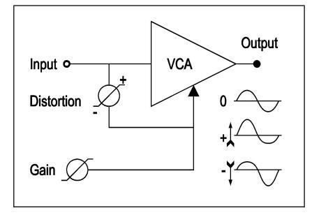
Next step in out filter design is to add a little distortion to mimic the non-linearities in an analog filter. The choice is between either even harmonic distortion or odd harmonic distortion. Even harmonic distortion is more interesting as it can make a filter appear both steeper and less steep. The idea is that even harmonic distortion in fact produces all harmonics except the fundamental of the distorted signal. These new harmonics can actually be subtracted from the undistorted signal, which makes the filter slope sound steeper. And by adding them to the filter output signal the filter will appear less steep. There is a simple trick to produce even harmonic distortion that works on all synthesizers that have a linear VCA and a means of inverting a signal. The idea is to use a fixed control voltage on a VCA control input in such a way that the VCA amplification is exactly one or unity gain. Then a little bit of the input signal into the audio input of the VCA is mixed with the fixed control voltage. When the input waveform is positive the gain of the VCA will increase slightly while when the inputs signal is negative the gain will be slightly reduced. It is like the signal is compressed when negative and expanded while positive. When set this way the VCA will generate the second harmonic of each sinewave partial that is present in the input signal. The amount of distortion is set by the amount and the polarity of the signal that is added to the fixed control value for the VCA. Beware that the maximum level of the modulation signal is about half the fixed voltage or control value, exceeding this value might cause some true analog VCA’s to stop working.
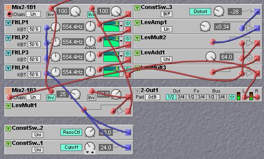
On the G2 even harmonic distortion is very easy to patch, the audio signal is fed into a multiplier module and the control input receives a control signal from a LevelAdd module that is set to +64. The +64 value will cause the multiplier to pass its input signal unaltered at unity gain. By feeding a bit of the input signal to the input of the LevelAdd module the multiplier will start to produce even harmonic distortion. Another multiplier, controlled by a knob control module that can be set between –64 and +64 units, controls the depth of the effect. This knob controls the amount of distortion and also if the generated harmonics are mixed in phase or in anti-phase. The useful range for the knob control is between –32 and +32. On the G2 the control value must be set to a negative value if the LevelAdd is set to +64 units, or the control must be set to a positive value if the levelAdd is set to –64 units, to create the proper type of even harmonic distortion.
The even harmonic distortion can be inserted in the filter resonance feedback path after the last 6dB filter. This has the advantage that the output of the filter can be the output of the harmonic distorter, so that both the filter and the resonance feedback can take advantage of the same distortion. This will make the filter slightly more grungy. The patch looks like this:
An interesting effect of even harmonic distortion is that it can make a filter appear to be a little bit steeper. Imagine that a single sawtooth wave is filtered with a filter set equal to the pitch of the sawtooth wave. The second harmonic will be suppressed by 24 dB, as it is one octave higher as the filter cutoff frequency. The first harmonic is basically passed through unaltered. The even harmonic distortion will produce a second harmonic signal from the first harmonic. If this second harmonic happens to be in reversed phase with the original second harmonic in the input signal, this generated second harmonic can be tuned in level in a way that it totally cancels out the bit of second harmonic that was still passed on by the filter. If the second harmonic generated by the distorting is in phase with the original second harmonic the filter will appear to sound less steep and give a slightly buzzy character to the filtered sound. So, with this even harmonic distortion one can go two ways in changing the timbre of the filter.
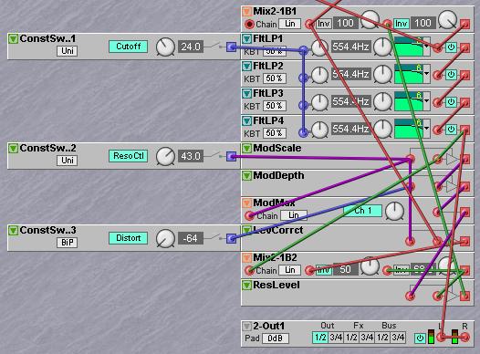
Another and simpler way to get the same type of grungy filter distortion is to make use of the gain controller in the resonance feedback path to create the asymmetric distortion. By adding the audio output signal of the last pole in the filter to the control signal of the resonance level gain controller the same type of distortion is produced. To accomplish this the filter output signal must go through two additional gain controllers, one that sets the depth and polarity of the resonance modulation signal and the second one to scale the modulation signal to the resonance depth. This scaling must be done to prevent the modulation signal to prevent the resonance modulation signal to have an effect when the resonance is low or zero. After the two gain controllers the modulation signal is added to the resonance control signal in a simple two input mixer. The green cables show the resonance feedback loop signal flow, while the purple cables show the resonance modulation signal flow.
What few people realize is that a basic 24dB filter actually has several inputs and outputs. The outputs are obvious; they are the direct outputs of the individual 6dB filters. Additionally there is a fifth output, which is at the output of the first mixer where the feedback signal is mixed back into the loop and just before the first pole. The inputs are less obvious, but you must realize that to get a signal into the basic filter a mixer had to be used before the first 6dB filter. By adding additional mixers right before the 6dB filters and after the outputs of the previous filters, four extra inputs are created. This works, as when resonating, the filter is basically a closed loop, and a signal can be inserted at any point you like. So, a 24dB four-pole filter with all the possible insertion and output points looks like in the following schematic:
As you can see the outputs are named 0dB, 6dB, 12dB, 18dB and 24dB. The trick to get a filter with a different passband characteristic, like a bandpass or a highpass filter, is to combine two or more of the outputs, using a mixer module to add or subtract (=add in antiphase) certain amounts of the output signals. There is one thing of importance to realize, the 24dB lowpass is the steepest slope possible, any mix of output signals will always create a lowpass slope that is less steep. E.g. a bandpass filter can have a whole range of possible slopes, but the HP slope of the bandpass response will eat away steepness from the LP slope, e.g. it is possible to have a bandpass filter with both 12dB HP and LP slopes, as that adds to a total of 24dB, but it is not possible to make a bandpass response with both 24dB HP and LP slopes. In this last case four more poles should have to be added to add to a total of 48dB.
The 0dB output always includes the clean input signal on its output. If the resonance is set to zero the 0dB output will simply pass the input signal unaltered as no signal comes back through the resonance feedback loop. But if the resonance is raised, a strong resonance peak will appear in the output signal, added to the input signal by the resonance feedback loop. This makes this type of filter similar to a sharp peak EQ filter with a modulatable peak frequency. This is a bit similar to a Wah filter with a very pronounced resonance. This ‘peak’ filter can be used musically to boost one single frequency in an audio signal, e.g. to create a superloud basskick in a sampled drumloop. Or a sharp whistling in a noisey wind sound effect.
To make a highpass filter an extra mixer module is needed, as one has to subtract the 24dB output from the 0dB output. Note that this type of mixing is a bit similar to simple primary school adding and subtracting, but instead of numbers it is frequency bands that get added or subtracted. The 0dB output passes the whole frequency range, so when the lowpass frequeny band is subtracted from the whole range on this output, it is the high frequency band that remains. In fact, the output of the extra mixer will regain what the lowpass output threw away, plus the resonance peak. The level on the HP output appears to be much louder as the LP output. The reason is simply that higher frequencies have more sonic energy. This can be solved by lowering the level of the input signal by some -6dB.
Subtracting the 12dB output from the 24dB output makes a bandpass filter with two 12dB slopes. The BP output will appear to have a relatively low level compared to the other filter outputs. This can be corrected somewhat by tuning the third and fourth pole about an octave lower. This will widen the bandpass bandwidth a little and lower the resonance frequency by about a fifth note.
By adding about 2/3 of the clean filter input signal to the BP output the filter will become a notch filter. The notch filter will appear to have a loud output signal, similar to that of the HP output.
An interesting alternative for the 12dB/12dB bandpass response is to subtract the output signal from the third pole from the LP output. This yields a bandpass response with a 6dB highpass slope and a 18dB lowpass slope. This bandfilter tends to sound more pronounced, the reason is that the low roll off slope doesn’t have to be that steep for the ear to give a definite highpass effect, while the steepness of the high roll off slope is much more significant to the ear. The output level however seems rather low and the fourth pole can best be tuned one octave lower to gain some more level.
By patching a five input mixer with invert options on each channel, manual ‘morphs’ between an unlimited amounts of curves could be made, but as all curves except the 24dB LP curve will be ‘less than 24dB’ the practical effect for much settings is minimal. It is better to just pick four options and use a four-position switch to select one of these options. However, there is one morph that does work out very well and this is the morph between a 24dB LP and a 12dB/12dB BP curve. This morph is achieved by gradually mixing the inverted 12dB to the 24dB output while the 24dB output stays at full level. This LP->BP morph can give a nice buzzy sound to the filter, depending a bit on the audio material that is being filtered. Alternatively, you can use the 6dB/18dB bandpass filter and subtract a controllable amount of the 6dB output from the 24dB output to create a morph for the filter curve. The following patch is an example of this 6dB/18dB filter, used here to create a classic bright string ensemble sound.
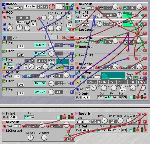
By detuning the 6dB curve you can set the width or aperture of the bandpass response to your own taste. Making the filter wider will decrease the resonance range slightly but also give less wobbly resonant filter sweep. It is best to set the bandwidth by ear to give just the effect that works out best on the filtered audio material. In the following example patch a four-position switch is used to select either a peak filter with clean feed if resonance is zero, a 24dB HP filter, a morphable BP/LP filter and a notch filter. The poles are equally detuned over two octaves to temper the resonance and widen the BP a bit. The detuning of the four 6dB filters causes the filter to not track the keyboard exactly anymore, which adds slightly to the analog feel.
The Aux insertion points in the basic filter schematic open up the possibility to mix signals in unusual ways, like mixing the HP part of one signal and the LP part of another signal and crossfade from one to the other through the audio spectrum. Just like different filter curves can be made by mixing two or more output points, different inputs can be made by routing one or more input signals to two or more insertion points.
A filter that has both a lowpass and a highpass input can be used to crossfade between the signals on the two inputs. Sweeping the cutoff frequency from very low to very high over the whole frequency range will fade one signal in from the low end, while the other is pushed away into the high end. If the cutoff is set to the highest maximum cutoff frequency of the filter virtually all of the signal on the lowpass input will be present on the output, but the signal on the highpass input will be almost fully suppressed. If the cutoff is set to the lowest possible cutoff frequency the signal on the lowpass input will be fully suppressed and the signal on the highpass input will be available on the output. When the cutoff is set to e.g. 800 Hz the signal on the output below 800 Hz will come from the lowpass input and the signal above 800 Hz will come from the highpass input. An interesting use of this sort of a filter is to e.g. replace the kick and bass in a drumloop sample by a kick and a bass from another drumloop sample. And all with only one filter. Another fine use is when two different waveforms from two detuned oscillators are fed into the two inputs. The filter envelope control signal will now also crossfade between the two waveforms through the sound spectrum. In this case it is often best to use a waveform with little harmonics, like a triangle wave or the output signal from a modulated FM oscillator, on the highpass input, and a bright waveform like a saw on the lowpass input. The block schematic of such a filter looks like the following diagram:
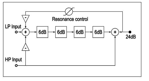
As you can see this filter is not much more complex as the standard 24dB lowpass filter.
On the G2 this filter is quite easy to patch. A basic patch looks like this:
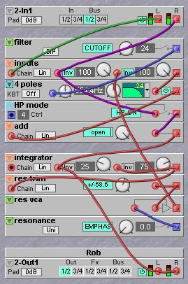
The green cable goes to the lowpass input, just like on the standard 24 dB filter that was described earlier. Extra is the purple signal that has two connection points in the patch, one goes to the input mixer where it is inverted and the other connection is made with an extra mixer right after the four poles and before the resonance feedback loop. The output of this mixer is also the output of the filter. There is an extra toggle button module named HP mode. This toggle button can switch the signal to the second insertion point on or off. If this switch is off the HP input becomes a LP input as its signal will only go to the input mixer. But when this switch is on the signal will also go to the second insertion point and the input will work like the HP input.
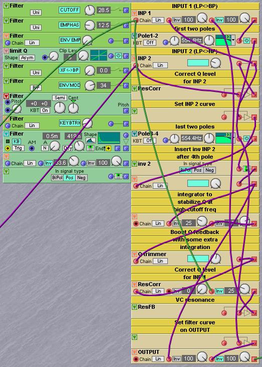
This two input filter can be be expanded with psycho-acoustic signal level correction when the resonance is raised. Additionally several output points can be mixed to change the filter curves of the two outputs. In the next patch example the signal levels are corrected for higher resonance settings plus a single control is added to change the curve of both the lowpass and the highpass inputs into two equal bandpass curves.
By using two additional panner modules on the input signals, where one panner fades in the opposite direction of the other one, two input signals can be ‘inversely’ crossfaded between either the highpass or the lowpass input. This creates a very interesting fader for two streams of audio material, where the two audio signals can be crossfaded in the traditional way or crossfaded through the audio spectrum. In a keyboard patch the filter can be used to mix two oscillators and thus create an interesting morph between two waveforms through the spectrum. In this last case it works best if the oscillator waveform on the highpass input has relatively little very high harmonics, like a triangle wave or a waveform created with a FM oscillator.