On analog modular synthesizers, which use cables to interconnect the available modules in the system, the cabling of a previous patch gets lost when a new patch is made. To be able to remake a patch later it is important to make a schematic drawing showing the cabling and the knob positions. Such a drawing is named a patchsheet. It is very important to make patchsheets on paper when the system has no provisions to store and recall patches by using some sort of patch memory.
It appears like digital systems with editor programs have made the use of patchsheets redundant. Still, it is a good custom to use paper to draw block schematics representing the structure of modular patches, as this creates a platform independent way to communicate about patches. In a block schematic each module or function is represented as a symbol. The symbols for modules and functions are interconnected with arrows, where the direction of an arrow shows the direction of the signal flow. In essence a block schematic represents a model. A model is a design which schematically shows all the aspects that are of importance in the design. Note that a model specifically refers to a ‘design’, and not to a brand or type of device. Manuals for analog prepatched synthesizers would always show the block schematic for the structure of modules and signal flows in the synth. By having a look at the block schematic it becomes immediately clear how many sound sources are present, how and where a modulation signal can be routed, etc. On a modular synthesizer each patch can be a different block schematic, which shows the power and flexibility of a modular system over a prepatched sytem. In a block schematic certain knob positions can be drawn or highlighted if these knobs have a special meaning in the patch, e.g. the knobs that are used to tweak the sound while playing.
On a digital synthesizer or a softsynth there is no apparent need to make oldfashioned patchsheets. Some softsynths use block schematics as a graphic interface to build patches, others use graphic representations of modules. With such systems block schematics on paper become even more important, as in a drawing on paper it is possible to group several modules that perform a certain function into a personalized symbol, a symbol that one can make up oneself. Symbols for sensors and mechanical input devices or even other synthesizer devices can be incorporated, when the block schematic is part of a score or a project description. So, no matter how elaborate the graphical interface for e.g. a softsynth might be, a block schematic on paper can always show more aspects of the project itself, aspects that happen outside the softsynth. There are many people that draw block schematics on paper to help bringing the stream of inspiration going or as a point of concentration while some deep thinking about a project is going on. Studying old block schematics can suddenly give new insights on the ideas expressed by the old schematics and inspire new projects. So, for several reasons it is a good idea to get familiar with block schematics.
Reading block schematics is quite easy, every block or symbol represents a physical module or function and following the arrows it quickly becomes clear what happens to the signals flowing between the modules and functions. In the western world it is customary to show the direction of a signal flow from left to right and/or top to bottom. This means that physical controllers or input devices, like keyboards, sensors, microphones, etc., are to be found at the top or on the left side. Sound sources are also often at this side, as sound sources deliver the source audio material to be processed later on in the patch. At the right side or bottom side one would typically find symbols for power amplifiers, loudspeakers or tracks on recording devices. Traditionally it was common to draw audio signal flows from left to right and draw modulation signal generators at the bottom with their signals flowing up into the symbols for modules that get modulated by the modulation signals. Today, there is a tendency to let signals flow downwards through symbols like a downwards pointing triangle for a mixer, the lower half of a circle for a sound source or signal generator, a full circle for a multiplication or controllable gain element, and annotations to the left side of a symbol to show details like the graph of a transfer curve or spectrum, etc.
There are no standardized rules how a block schematic or a symbol for a specific module should look like. Basically a block schematic and its symbols should simply be selfexplanatory. Still, there are some defacto standards on how e.g. a computer algorithm can be represented in scientific research papers or patent descriptions. But these defacto standards only standardize basic mathematical functions and do not include symbols for e.g. a distance detection sensor used to control the pitch of a sound source. Such a symbol can be devised by oneself. The amount and detail of the information in a block schematic depends fully on its purpose, e.g. if it is just a sketch for an idea or part of a score to be used by others.
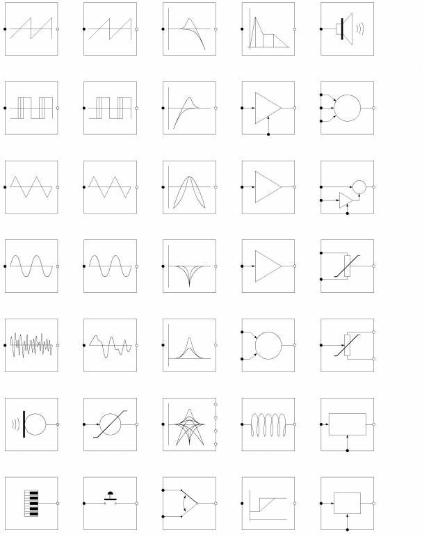
Figure 1 shows an example on how symbols in a block schematic for a modular synthesizer patch could look like.

Figure 1 – Examples of symbols for common synthesizer modules