The Nord Modular G2 features audio delayline modules that can be put to good use for on the fly capturing and manipulation of audio loops. The most versatile G2 delayline module for this purpose is the DelayQuad module. It features four tap outputs that can all be set to a different delay time in respect to the input. Maximum delay time is 2.7 seconds, which is equal to about a bar of audio at 90 BPM. Which means that if a full bar must be captured the tempo must be 90 BPM or faster. If the tempo of the bar to be captured is faster than 120 BPM the delayline module can be set to use 2.0 seconds of delay, which saves some delay memory that can be used by other modules, like a reverb or a pitch shifter module. A standard G2 uses four DSP chips, each with its own independent audio memory, so a standard G2 can capture four separate bars of audio at 90 BPM and faster. An expanded machine, which has eight DSP chips, can capture eight separate bars.
Recirculator principle.
On a vintage three-head reel-to-reel taperecorder, like e.g. the once extremely popular Revox A77, the tape first passes the erasure head, then the recording head and then the playback head. But it was not uncommon in the experimental tape studio to change the order of these heads by remounting the playback head first, then the erasure head and then the recording head. Mounting the heads in this order offered a new possibility to continuously overdub the audio on the same tape with only a single taperecorder. The tape first passes the playback head and outputs the audio on the tape to the playback output of the recorder, after which the audio is erased on the tape. The tape output signal is mixed with new audio material and then rerecorded on the tape at the record head position, which results in a build up of audio layers on the tape when e.g. an endless loop of tape is used. The method was already in use in the 1950's in the WDR studio's on Köln, where Stockhausen recorded his tape compositions. This same technique was later used in tape echo devices like the CopyCat and the Roland Space Echo. When the idea is to create a loop that must loop at a continuous volume and not die out like an echo does, the technique is often referred to as audio recirculation and a device that can do this is named a recirculator.
A taperecorder is not an ideal machine for this recirculation technique, as on every rerecording of the audio material the signal quality slightly decreases, and the audio will eventually either drown in noise or produce an overly saturated sound. But by using digital memory the audio can loop forever without any degradation. In the preparation for this article a two second loop on the G2 was made to recirculate for two days, and still sounded as fresh and crisp as when it was captured.
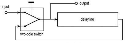
The basic patch uses a two input switch on the input of a delay memory. One input of the switch is connected to an audio source and the other switch-input is connected to the output of the delay line. If the switch is set to the audio source, this source is connected to the delayline input and audio will flow into the delayline. When on a certain moment the switch is toggled to the other position, the output signal of the delayline is connected to its input. This will cause the audio contents of the delayline to loop endlessly, until the switch is toggled to the audio source again. By connecting a 'momentary switch' module to the control input of the two-pole switch module, and assigning this 'pushbutton' module to a G2 frontpanel pushbutton, the capturing can be easily controlled by this frontpanel pushbutton.
Single loop patch.
The length of the loop will be exactly equal to the delaytime setting of the delayline. Which brings us to the issue of how to control the delaytime and so the loop length. On the G2 it is easy to control the delaytime automatically with the G2 Masterclock. To do so simply set the DelayQuad module to Clk mode with the Time/Clk button on the module. The Masterclock and so the loop time can now be conveniently controlled from the G2 frontpanel. When a Midiclock signal is sensed on the Midi In connector and the G2 is set to receive Midiclock, the delaytime will automatically adjust itself to the tempo of the incoming Midiclock signal. But this must be an absolutely stable Midiclock signal and not all Midi sequencers and sequencer programs produce stable Midiclock signals. It is more reliable to actually use the G2 as the Midiclock master and sync the other devices to the G2 Midiclock. This will guarantee absolutely stable delaytimes on the G2 delay modules.
When the DelayQuad module is set to Clk mode the delaytime of each tap can be set to a subdivision of the BPM tempo. To capture exactly one full bar of audio at the masterclock BPM setting the subdivision must be set to 2/1, or the knob fully open.
There are two main points where the audio can be tapped from the recirculator, one point is at the output of the two-pole switch and the other is at the output of the delay line. If the output is taken from the switch output the output of the recirculator will immediately output the incoming audio when the loop is set to capture, meaning that when pressing the capture pushbutton you will 'monitor' the input signal while capturing, until you release the capture button. If the output is instead taken from the output of the delayline and the capture button is pressed, you will not hear the input signal until the next bar, as the audio first has to pass the delayline, which takes a while. Many times you would probably want to hear the new audio immediately, so the output of the switch is the most often used output of the recirculator. There is one situation where you will have to use the output of the delayline and not the switch. This is necessary when the output of the delayline is fed into some extra effects and you want to create an extra feedback loop where the loop signal plus the effects are mixed together with the audio input signal. In this case the audio from the currently looping signal can only be taken from the delayline output. This is definitely a more advanced and a bit tricky way of looping, so for now start by using the output of the switch and experiment with the delayline output only when you fully understand the looping mechanism. The other three outputs of the delayline can of course be used to tap the audio as well.
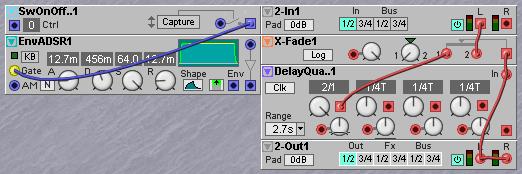
When a two-pole switch is used on the input of the delay module, the toggling of the switch will most probably introduce a click. To avoid this click it is better to use a crossfade module and control the crossfade position with an ADSR envelope with a short attack and release time and full sustain level. This ADSR envelope can be controlled by a 'momentary switch' module that is assigned to one of the G2 frontpanel pushbuttons. One of the outputs of the QuadDealy module is connected to the first input of the crossfader module and the audio to be captured is connected to the second input. The crossfader knob is set fully to the left, and the ADSR envelope is connected to the crossfader modulation input. If the modulation amount control knob is set fully open, the crossfader will act as a soft switch where the attack and release times set the soft edges of the switching. There is another advantage when using a crossfader instead of a toggling switch, as when the modulation amount control knob is set half open the audio will not be replaced, but instead be mixed to the recirculating output of the delayline and the loop can be made to build up with additional layers of audio.
The next issue is how to get more simultaneous loops, like when using the four tracks on a four track taperecorder loop. When the previous patch example is set to four voice polyphony there are in fact four parallel loops, as each voice will in fact be an independent loop. The point is now how to discriminate between the four voices. In other words, how can only a particular voice be forced to capture audio while the other loops just keep on looping. To be able to do this the Status module must be used. This module has an output named 'Voice No.' and this output will generate a value that is different in each voice. This output can be used to directly control the Mux multipole switch modules. The idea is to use a Mux8-1 module at the input of the recirculator and a Mux1-8 module on the output of the recirculator and control the Muxes with the Status module. At the Gate input of the ADSR module is also a Mux 8-1 module and several pushbutton modules are connected to the inputs of this Mux8-1 module, like in the example. On a standard G2 you can make four loops, using the DSP memory of each of the four DSPs for each loop. On an expanded G2, with its eight DSPs and memory, you can make eight paralllel loops. In the example each loop has its own physical audio Line In input. The outputs of the loops are mixed with the four channel mixer, but you could alternatively route each loop to one of the four physical Line Out outputs. It is also possible to get the audio from patches in other slots by using the four G2 internal audio bus lines.
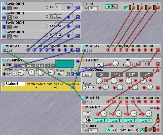
Four-track loop patch.
Effect modules can be patched after the mixer in which case all loops will flow through the effect. But it is also possible to use an effect like e.g. a distortion on each individual loop and have individual distortion settings for each loop. In this case only one distortion module is necessary and it can be placed between the output of the recirculator and the input of the Mux1-8 module. To give each loop its individual settings the SeqCtrl module can be used. By controlling the SeqCtrl module from the Voice No. output of the Status module the first four step sliders will actually provide the individual control values for the four voices. Just assign the first four sliders to frontpanel knobs and you have the individual control knobs.
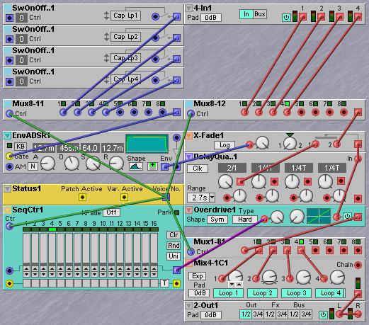
Individual loop settings.
With this 'live sampling' technique of capturing audio into loops using this 'polyphonic recirculator patch', you can actually mix a whole live performance set with audio that comes from other slots in the G2, audio from samplers, drum computers, record players or a CD player, the Mic input or from the instruments played live by other musicians you perform with. It is a powerful live technique that the G2 can do quite well, though you will probably need some practicing to master it.